Introduction: Gutenberg Printing Press Printed on a 3D Printer


Recently I learned about Johannes Gutenberg, the inventor of the printing press, at school. At the time his press revolutionized how text and information was spread and set the foundation for modern day printers, digital fonts and typefaces. I was immediately intrigued and I had to recreate the printing press myself.
I'm a 7th Grade Student at the Maria von Linden Gymnasium
Supplies
Supplies
- 3D Printing Filament
- Acrylic or Oil Based Inks
- Leather/Goose skin/Cloth (Gutenberg used goose skin, I used a faux leather cloth)
- A6 Paper (148mm x 105mm / 5.8in x 4.1in)
- String
- 1 - 1.2 mm diameter wire/nail
- Wool
- Sandpaper
Tools
- Fusion 360
- 3D Printer
Step 1: Research
I didn't know a lot about how the press functioned so I had to research and take notes
Here are some of the websites and videos I used:
https://www.printmuseum.org/gutenberg-press
https://www.youtube.com/watch?v=DLctAw4JZXE
Here is the general process from single letters to a finished page
- Individual letters were cast from a metal alloy
- These letters were then placed into the bed and were clamped in place
- After that, a thin layer of ink was rolled onto the letters using 2 ink balls
- Next a page was placed between the tympan and the frisquet and folded onto the inked letters
- The bed was slid under the main press
- The pullbar was turned, twisting a large screw and lowering the platten
- Then the pullbar was tightened and the platten pressed the ink onto the page
- Finally pressure was released using the pullbar, the bed was taken out and the tympan and frisquet were folded back open to reveal the finished page
Step 2: Sketching
With large projects like this one it's really helpful to create quick drawings to easily see if you design could work or is just fatally flawed. In the end I came up with the design above.
Step 3: Outline of the Base
- I started off by roughly sketching the cross section of the press using rectangles and lines on the xz plane
- Next I added dimensions and constraints to fully constrain the sketch
- After that I extruded the resulting sketch 30mm as a new component
Step 4: The Thread in the Base
For printability reasons I wanted to make the angle of the threads I was going to make 45 degrees instead of 30. Additionally I wanted both threads from the middle horizontal bar and the lower horizontal bar to be perfectly in sync. To achieve all of this I had to use a bit of trickery
- First I extruded the rectangle between the lower and middle horizontal bars from my first sketch
- Then I created a sketch on the bottom face of the lower horizontal bar
- Next I created a 20mm diameter wide circle and extrude-cut it through the lower horizontal bar
- After that I scaled the base down on the z axis by 30/45 = 66.6666%
- Then I added the threads using the Fusion thread modeling tool (I made sure to click "Modeled" otherwise the thread would not show up on the final part)
- After that I scaled the base up on the z axis by 45/30 = 150%
- Finally I extrude-cut the rectangle between the lower and middle horizontal bars from my first sketch
Step 5: Creating the Threaded Rod
- To create the base part of the threaded rod, I extruded the same circle from the 2nd sketch up 110 mm and down 30 mm and made sure to make it a new component
- Then I scaled the rod down on the z axis by 30/45 = 66.6666%
- After that I added a thread using Fusion 360's thread feature
- Finally I scaled the threaded rod up on the z axis by 45/30 = 150%
Step 6: Rails for the Sliding Bed
- To create the rails for the sliding bed I started off by creating a sketch on the side face of the base
- I created 2 equally sized rectangles and added small "<" shaped cutouts to both sides
- Finally I just extruded both outer shapes out 160mm
Step 7: The Sliding Bed
- To create the sliding bed I edited the previous sketch and connected the upper and lower spikes using lines
- Then I created a vertical line offset 10mm from the spikes on either side
- After that I created a horizontal line offset from the lowest horizontal line 5 mm
- After that I extruded the u-shaped polygon 140 mm
- Finally I added ends to both open sides of the newly created body using 2 extrude features
Step 8: Adding a Clamp Part 1
I wanted to be able to clamp the text in place in the same way the Gutenberg Press did it
- To do this, I created a sketch on the back face of the sliding bed
- Next I sketched a small rectangle in the center of the face and a smaller circle with a diameter of 8mm in the center as well
- After that I extruded the drawn rectangle out 10mm and cut a hole through it using the circle from the previous sketch
- Once that was done, I added a thread to the inner bore
Step 9: Adding a Clamp Part 2
Next I designed the screw
- I extruded the circle from the previous sketch out 40 mm
- Next I added a thread to this rod
- After that I created a sketch on one of the end-faces and sketched a slightly larger circle concentric with the first original circle from which the pin was extruded
- Finally I extruded this larger circle out 8 mm and joined it with the threaded component
Step 10: Adding a Clamp Part 3
Lastly, to complete the clamp I designed the slider
- I created a sketch on the topmost face
- Next I drew an upside-down 'u' shaped polygon around the edges of the base
- To decide how much the slider could move I drew long thin rectangles on the top face of the base
- After that I extrude-cut these long thin rectangles on either side down
- Finally I extruded the upside down 'u' shaped polygon to finish the slider
Step 11: The Paper Holder
- To create the sketch for the paper holder I started off by creating a sketch on the top face of the base
- Next I created a A6 sized rectangle to the side of the base
- Then, I added an offset of 4 and -4 mm
- To finish off the sketch, I extended the inner offset all the way to the edge of the outer offset
- Next, I extruded the outermost area (shaped like an upside down u) up 4mm
- After that I extruded the innermost area (also shaped like an upside down u) up 1mm
- Finally I two-side-extruded the previous shape up 4mm and -3 mm
Step 12: Linkage Between the Paper Holder and the Bed
- Next I created a sketch on the side of the base and drew a large circle with a diameter of 8mm on the top corner of the base
- After that I drew 2 smaller circles concentric to the first one (one with the diameter of 1.4 mm and one with the diameter of 2mm)
- Then I extruded the outer ring into the base 15mm
- Next I two-side-extruded the outer and inner ring into the base 15mm and -30mm as a new component
- I repeated the previous step but this time I cut the created form into the bed
- I copied the previous three steps on the other side
- To finish off the joint I extruded the side face from the paper holder into the two other components and joined them
Step 13: Adding Joints
I wanted to animate my design and see how it would function in Fusion 360, so I had to use joints.
Fusion 360 makes it really easy to add joints to designs. Because I had designed all the parts in place, I only used 'As Built Joints"
- I started off by creating a revolute joint around the linkage of the paper holder and base
- Next I created a sliding joint along the rails of the base and bed
- After that I created a cylindrical joint on the small slider thread
- To synchronize the side to side and rotational movement of the cylindrical joint I added a motion link
- Finally I repeated the last two steps on the larger thread
Step 14: Using the Joints
I checked if all the joints were working so far and moved the bed under the base for the next few steps
Step 15: Creating the Pullbar Attachment
- To create the Pullbar Attachment I created a sketch on the 4th face from the top
- I drew a 2 concentric circles in the center of the face (one with a diameter of 20 mm and one with a diameter of 35 mm)
- Next I extruded the ring down 35mm and added a 45 degree thread to the inner portion using the same technique as in step 4/5
Step 16: Creating the Platter
Creating the platter was quite simple:
- All I had to do was create a sketch on top of the bed
- Then I created an A6 sized rectangle
- Next I applied an inner offset to the first rectangle
- I extruded this rectangle up 5mm
- Finally I filleted the edges
Step 17: Solution for the Rotating Platter
At this point I was stuck. I wanted the threaded rod to be able to move the platter up and down, but not rotate it. I thought about using rubber bands or guiding tracks on the side, but these designs had several issues. I examined the footage of a working printing press once more in slow motion and the simple solution struck me. A carriage embedded into one of the bars in the base would move up and down on a simple rod and the platter would be held in place using string. Once you wanted to press into the paper, the carriage would move down and eventually the string would go slack and wouldn't hinder the pressing process.
Step 18: Designing the Carriage
- To create the carriage, I started by creating a sketch on the top face of the lowest bar on the base
- I drew a rectangle in the middle of the face and drew a smaller circle with a diameter of 15 mm at the center of the newly created rectangle
- Next I extruded the outer polygon down 15mm
- To allow space for the carriage to slide I extrude-cut the outer polygon into the thread and the base
- Finally I split the carriage in half to be able to assemble it
Step 19: Hooks to Connect the Carriage and the Platter
Creating the hooks was very repetitive
- I repeatedly drew circles on the edges
- Then I split these circles into quarters
- Next I applied an inner offset to these quarter circles
- Finally I extruded these quarter circles and filleted the edges
Step 20: Creating the Pullbar
- To create the pullbar, I drew a circle on the xz-plane with a diameter of 10mm
- Then I extrude-cut this sketch to cut through both the attachment for the pullbar and the thread
- Finally I extruded the circle 65mm to form the pullbar
Step 21: Widening the Threaded Rod at the Bottom
The original printing press used a thin metal pole to apply the pressing force. However 3D prints are not as strong as metal, so I had to widen the base to distribute the force more evenly
- I created a sketch on the platter and drew a circle with a diameter of 50mm
- Next I extruded this circle up using a taper angle of 45 degrees and joined it with the threaded rod
- Lastly I filleted the sharp edge at the bottom
Step 22: Decor
I wanted my printing press to look a lot like the one at the international printing museum. So I focused on the ancient style of the printing press next
- I started by creating a sketch on a side face on the base
- Then I used rectangles to outline the general shape of all the curves
- Next I filleted all the interior edges
- After that I extruded these curves on all four sides
Step 23: Decor Part 2
I used a similar technique to enhance the top part:
- I drew three rectangles in the center of the face
- Then I extruded these rectangles and filleted the interior edges
Step 24: Side Decor
The original printing press was held together by large planks slotted together. You can still see these planks partially protruding on the outside. Even though 3D Prints are not made of planks, I still wanted to include them because I thought that they add to the ancient feel of the press.
- To create these planks I drew various rectangles in one column replicating the design seen on the original printing press
- Then I extruded these rectangles at varying depths, judging the distance by eye,
- Finally I mirrored these features on the other side
Step 25: Logo on the Side
The printing press that I was copying (from : https://www.printmuseum.org/gutenberg-press) had a logo on the side as well. I however could't decipher what was on the logo, so I used my username and the year to create a similar logo in the same style. To do this I used ellipses and text which was extruded and copied on the other side
Step 26: Filleting Edges
Any design looks way better when you add fillets. That's why I added fillets everywhere (on the base, pullbar, attachment for the pullbar, slider, etc..)
Step 27: Choosing a Font
So many more fonts exist than text editors like Microsoft Word display. Because I was recreating the original printing press made by Johannes Gutenberg, I wanted to use the font that he used. However his font (Gutenberg Textura : First Picture) was not legible to me for a variety of reasons : u and v look the same, x looks like an r, M and W look the same, I looks like q...
In the end I chose a font named Augusta (Second Picture), which had a similar feel, but I could actually read it this time.
To use the font all I had to do was (only applies to Macbook):
- Download the font file from a website like https://www.fontsquirrel.com/fonts/list/recent
- Open the Fontbook
- Open the font file
- Press install
- Restart Fusion
Step 28: Creating the Letters
Creating the letters was very repetitive and tedious.
- I started by creating a rectangle with a 10mm height
- Next I put a text box on the rectangle and wrote a letter in the lower center (using Augusta Font and 10pt size)
- I adjusted the text box and rectangle to fit the letter perfectly
- Then I extruded the letter up 16 mm
- Finally I extruded the rectangle up 14 mm
- I repeated this for all the letters in the word "Instructables"
- Lastly, I mirrored all the letters
(I know this is not the best way to do this. Professional font designers focus a lot on kerning (spacing between letters). This makes special combinations of letters look best. In letter combinations like VA the boxes around the letters would overlap but leaving them like this is the most pleasing to the eye. If you want to learn more you can read this : https://www.fontfabric.com/blog/good-kerning-gone-bad-tips-fail-examples-recognize-signs-mistakes/ )
Step 29: Instructables Robot Logo
- To create the Instructables Robot Logo I uploaded an svg of the logo into Fusion 360.
- The logo had very thin sections so I offset all of the lines 0.3 mm for printability
- Next I sketched a rectangle around the logo and extruded it up 14 mm
- Finally I extruded the logo up 16 mm and mirrored it
Step 30: Adding Offsets for Clearance
A 3D Printer is not very accurate so you have to add clearance to every part :
- The linkage between the paper holder and base
- The main thread
- The clamping mechanism
- The pullbar
- The carriage
Step 31: Inkballs
2 ink balls were used to apply ink to the text (rollers hadn't been invented yet). I created these last
- I started by drawing a semicircle and adding a rectangle as a handle to it
- Next I filleted the edges of the rectangle and proceeded with drawing a u shaped line separating handle and base
- Then I offset this us shaped path 5mm created a line through the middle of the entire sketch (this will be the revolving axis)
- Finally I revolved the handle and front part around the axis created
Step 32: Printing
Base
Material : Gold/Brown PLA
Orientation : As is (Support is optional)
Bed
Material : Gold/Brown PLA
Orientation : As is
Paper Holder
Material : Gold/Brown PLA
Orientation : As is
2x Carriage
Material : Gold/Brown PLA
Orientation : on the side opposite to the circular cutout
Main Thread
Material : White PLA
Orientation : As is
Slider
Material : Gold/Brown PLA
Orientation : As is
Pullbar
Material : Black PLA
Orientation : As is (moved down 0.4 mm for bed adhesion)
Small Screw
Material : Gold/Brown/White PLA
Orientation : On the screw head
Platter
Material : Bottom : TPU Top : PLA
Orientation : As is
Movable Type (I, n, s, t, r, u, c, a, b, l, e, ClampingBlock1, ClampingBlock2)
Material : PLA
Orientation : As is
Pullbar attachment
Material : Bottom : Black Middle : Gold/Brown Top : Black
Orientation : As is
2 x Ink Ball Handle
Material : Gold PLA
Orientation : Plat side on the bottom
2 x Ink Ball Top
Material : PLA
Orientation : Plat side on the bottom
Attachments


Step 33: General Assembly
Assembly is a lot like a puzzle
- Put both halves of the carriage onto the large thread
- Push the thread through the first hole from the bottom in the base
- Screw on the Pullbar attachment
- Screw the main thread into the top hole in the base
- Push the Pullbar through the hole in the Pullbar attachment and the thread (make sure both holes are aligned)
Step 34: General Assembly Part 2
- Secure the Platter onto the carriage by threading string through the holes and tying a strong knot
- Cut 2 3 cm long sections of wire and, while holding the paper holder in place, push them through the holes and secure them with hot glue on one side only
- Slide the bed in place
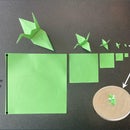
Step 35: Assembly of an Ink Ball Part 1
I repeated this twice to get 2 Ink balls
- Cut out a large leather disk around 3x the size of the ink ball top
- Fill it with wool
- Place the ink ball top over the wool
Step 36: Assemble of and Ink Ball Part 2
- Fold part of the leather over and into the cavity
- Work you way around the whole leather circle folding in the leather as you go (this can be tricky because you have to hold your previous fold in place with your other fingers)
- Clamp it all in place by squeezing the ink ball handle into the cavity
Step 37: How to Operate Part 1
- Start by clamping all your text in the bed
- Place an A6 paper into the paper holder
- Roll the ink balls in some acrylic ink mixed with water / oil paint
- Roll the ink balls together to get an even spread of paint
- Spread the paint evenly on the text. You want a thin even layer and no large globs
Step 38: How to Operate Part 2
- Fold the Paper holder onto the bed and slide it into the press
- Turn the handle tightly
- Reverse
- Pullout the bed
- Open the paper holder to reveal the paper
- Repeat and feel the astonishing speed of 15th Century mass production
Step 39: Troubleshooting
At first my paint would dry out immediately and no/little print mark was left. I though I had too little paint on the letters, but in the end the solution was to add water. After I had fixed that, my letters still wouldn't print nicely on the paper. Sanding the top face down with a high grit sandpaper did the trick.
Step 40: Conclusion
This was an awesome project. I learned how to use Section Analysis, Components, Joints and Constraints in Fusion 360. I do not regret spending all this time to learn, about the Gutenberg Printing Press. This printing press is the prefect demo to showcase the skill and hard work you had to have to operate a printer in the 15th century and it also showcases how far we've come from the days of The Gutenberg Printing Press.

Judges Prize in the
Text Contest


